Skip to product information
1 of 6

electrical center b2c

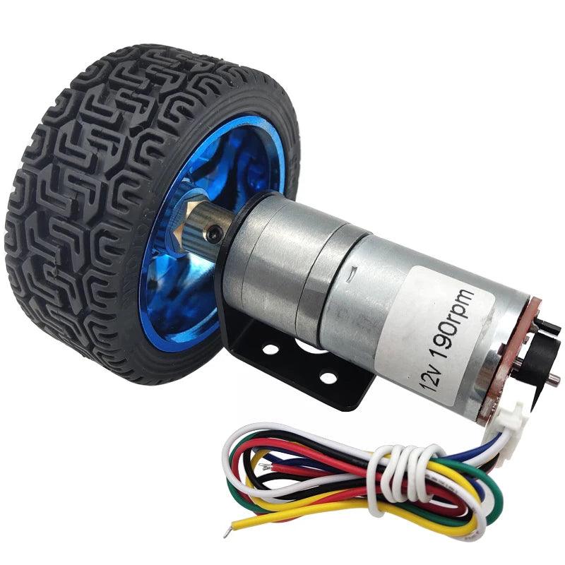
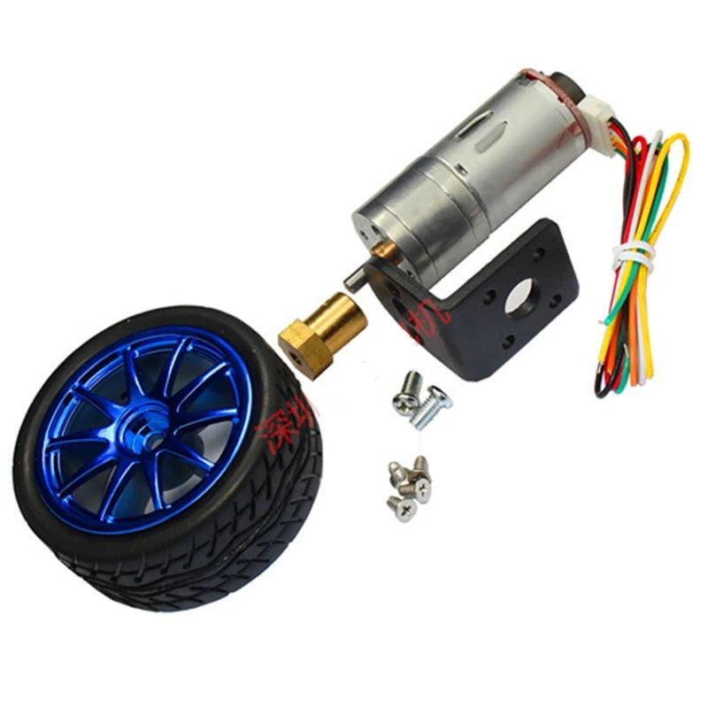
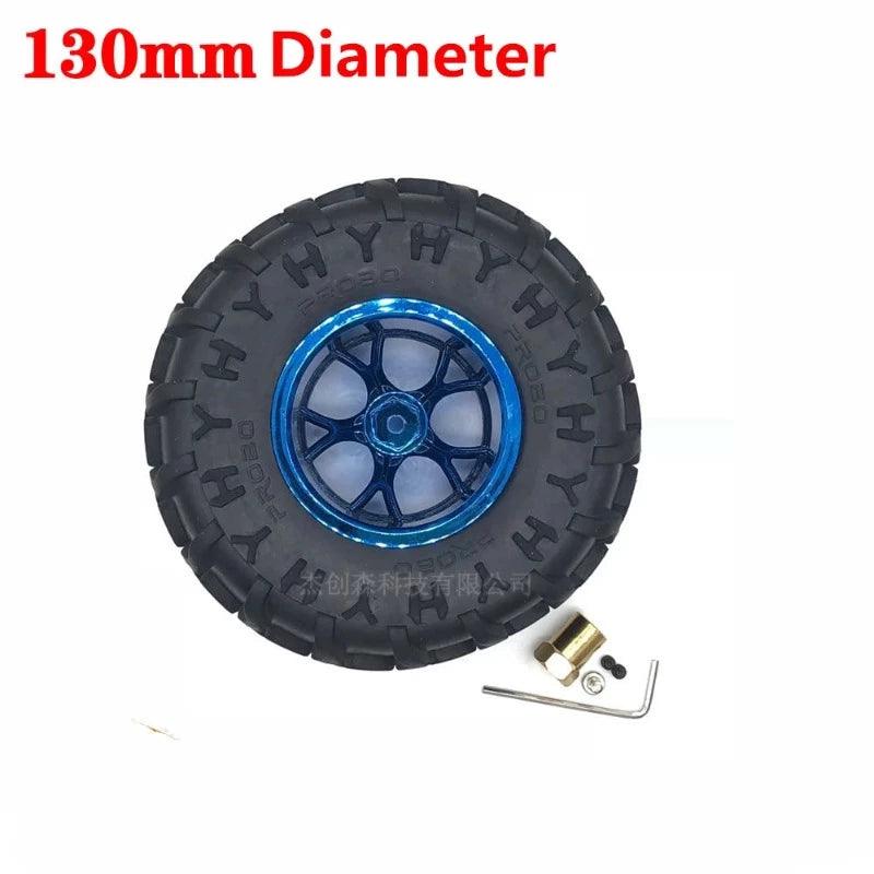
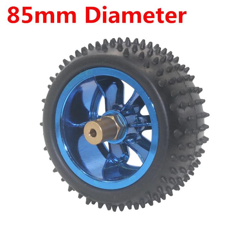
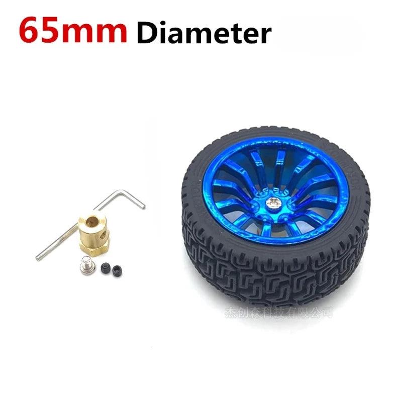
65mm 85mm 130mm Wheel Hub Motor Kit Encode DC 6V 12V 24V Speed 12- 1360rpm Metal Gearbox Encoder Moter RC Car Robot JGA25-370

Regular price $47.55 USD
Regular price $49.48 USD Sale price $47.55 USD
Sale Sold out
Shipping calculated at checkout.
Voltage(V)
Speed(RPM)

SPECIFICATIONS

65mm 85mm 130mm Wheel Hub Motor Kit Encode DC 6V 12V 24V Speed 12- 1360rpm Metal Gearbox Encoder Moter RC Car Robot JGA25-370

Brand Name: HYSMOTOR

Certification: CCC

Certification: ROHS

Origin: Mainland China

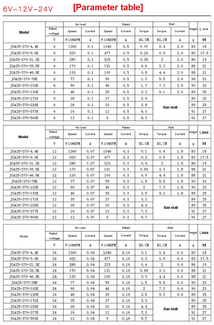
Continuous Current(A): 100ma

Output Power: 3W

Commutation: Brush

Type: Gear Motor

Protect Feature: Totally Enclosed

Construction: Permanent Magnet

Usage: BoAt

Usage: car

Usage: Electric Bicycle

Usage: Fan

Usage: Home Appliance

Efficiency: IE 1

Model Number: JGA25-370 Encoder Motors

Torque: max 8kg.cm
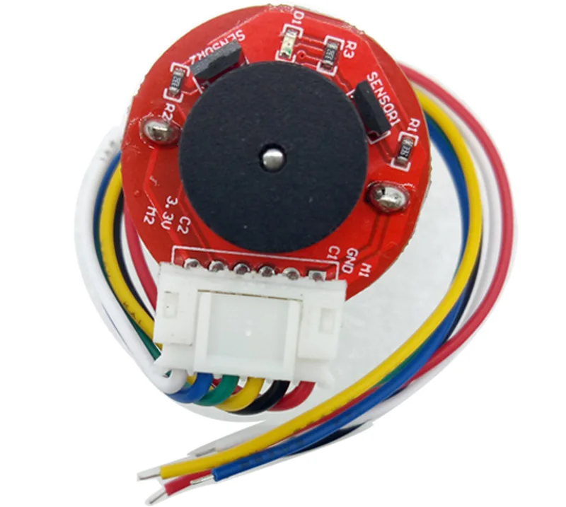

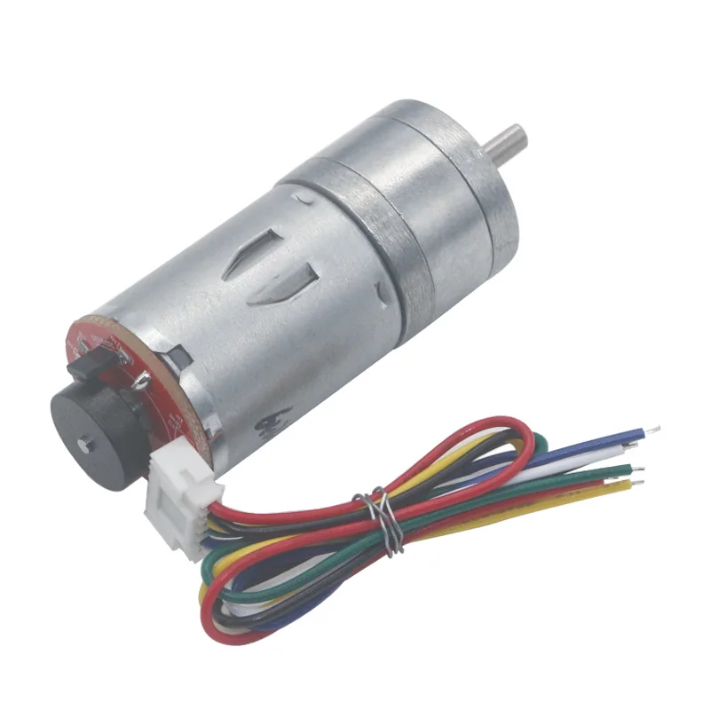
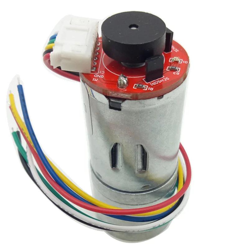
Hall encoder introduction
1. Outer diameter size: 25mm
2. Number of Halls: 2 Hall elements have a two-phase AB output, Hall is a unipolar Hall
3. Magnetic ring material: diameter 14mm; thickness 5.5mm; encoder inner hole suitable for mounting motor shaft diameter 2mm
4. Hall voltage: 5V/3.3V
5. Line speed : Basic pulse number 11PPR ; The motor rotates one turn and outputs 11 pulses.
6. Basic functions: It has a pull-up shaping resistor, and the MCU can be directly connected.
7. Interface Type : PH 2.0
8. Output signal type : Square wave AB phase
9. Response frequency : 100KHz
10. The number of magnetic ring trigger stages is 22 (11 pairs)
11. Gearbox resolution of the motor = 11 pulses * reduction ratio
Line Wiring Method
1. Red line : DC power supply positive pole connected to the motor
(Control the clockwise or counterclockwise rotation of the motor by changing the way the positive and negative electrodes are connected
2. Black wire : The negative power supply required to connect the encoder 3.3V / 5V
(Note: the positive and negative poles cannot be connected incorrectly)
3. Yellow wire : signal feedback line; The motor rotates one turn and outputs 11 signals.
4. Green line : signal feedback line; The motor rotates one turn and outputs  11 signals.
5. Blue line : The positive power supply required to connect the encoder 3.3V / 5V
(Note: the positive and negative poles cannot be connected incorrectly)
6. White wire : Connect the negative DC power supply of the motor
(Control the clockwise or counterclockwise rotation of the motor by changing the way the positive and negative electrodes are connected)

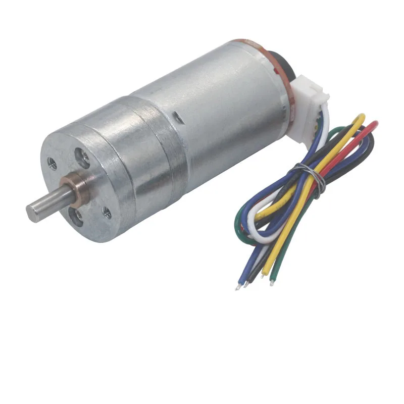
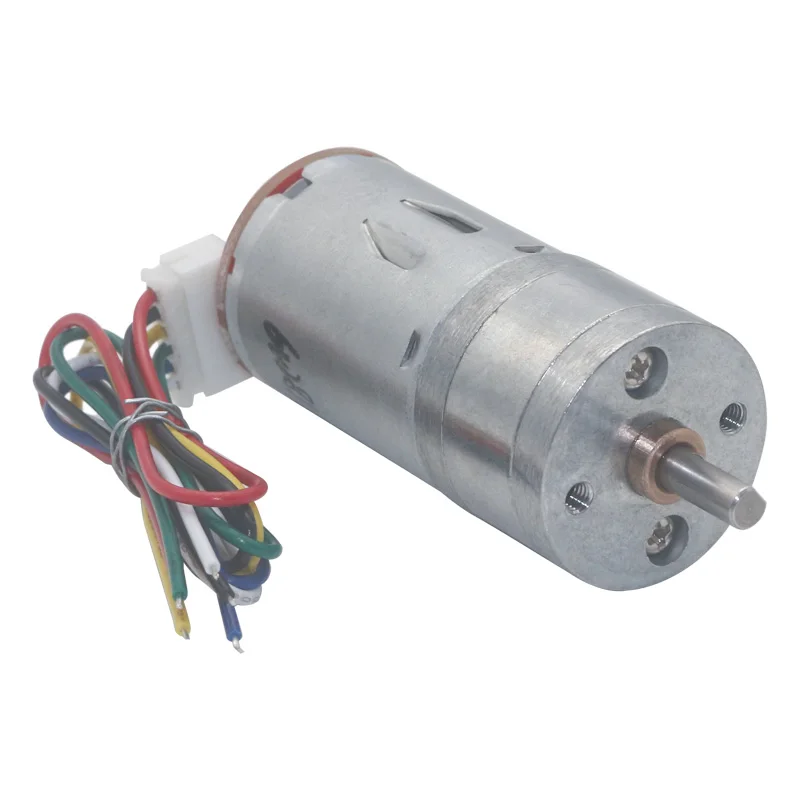
The following is the picture of the motor


Wiring method:

  • Red Wire - positive power supply of motor(+)(change positive and negative of motor the rotation will change)

  • White Wire - negative power supply of motor(-)(change positive and negative of motor the rotation will change))

  • Yellow Wire - signal feedback (motor one turn has 11 signals)

  • Green Wire - signal feedback (motor one turn has 11 signals)

  • Blue Wire - positive of encoder power supply(+)(3.3-5V),cannot be wrong

  • Black Wire - negative of encoder power supply(-)(3.3-5V),cannot be wrong


Care Instructions

Customer Reviews

Be the first to write a review
0%
(0)
0%
(0)
0%
(0)
0%
(0)
0%
(0)