Skip to content


electrical center b2c
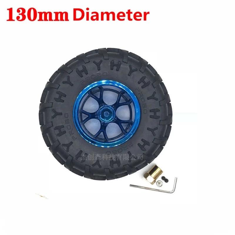
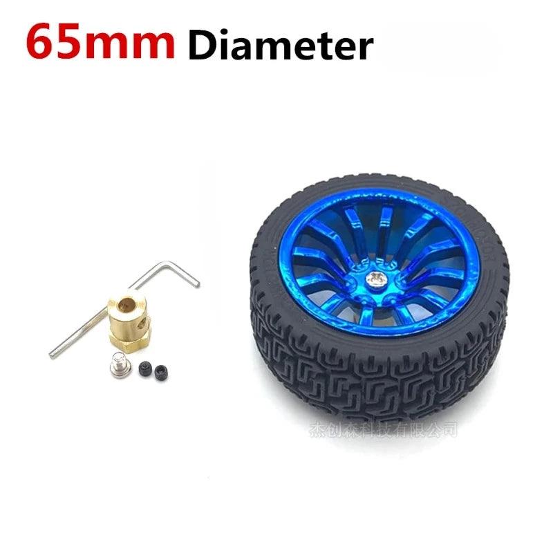
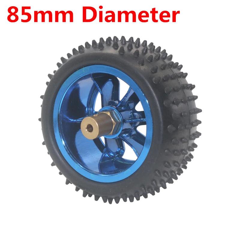
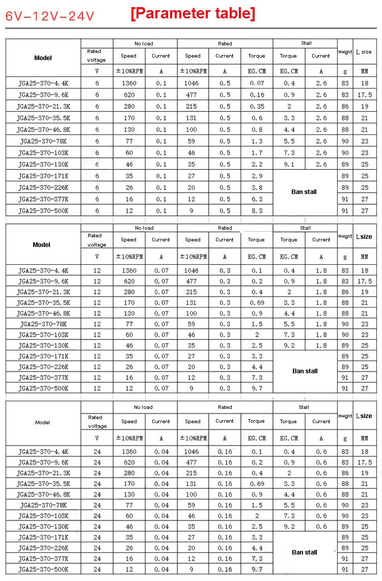
65mm 85mm 130mm Wheel Hub Motor Kit Encode DC 6V 12V 24V Speed 12- 1360rpm Metal Gearbox Encoder Moter RC Car Robot JGA25-370
Couldn't load pickup availability
SPECIFICATIONS
65mm 85mm 130mm Wheel Hub Motor Kit Encode DC 6V 12V 24V Speed 12- 1360rpm Metal Gearbox Encoder Moter RC Car Robot JGA25-370
electric hub motor for car,hub motors,wheel motor
Brand Name: HYSMOTOR
Certification: CCC
Certification: ROHS
Origin: Mainland China
Continuous Current(A): 100ma
Output Power: 3W
Commutation: Brush
Type: Gear Motor
Protect Feature: Totally Enclosed
Construction: Permanent Magnet
Usage: BoAt
Usage: car
Usage: Electric Bicycle
Usage: Fan
Usage: Home Appliance
Efficiency: IE 1
Model Number: JGA25-370 Encoder Motors
Torque: max 8kg.cm
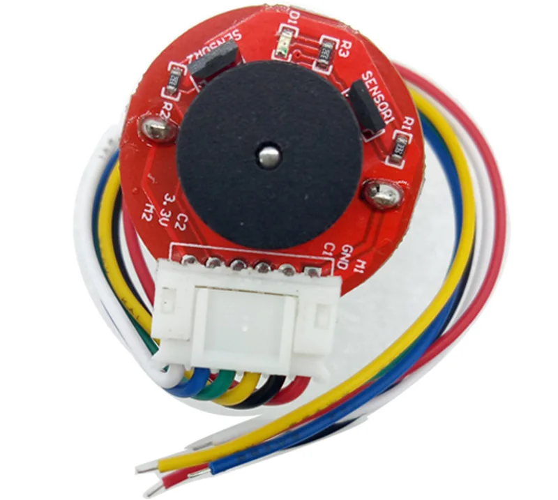
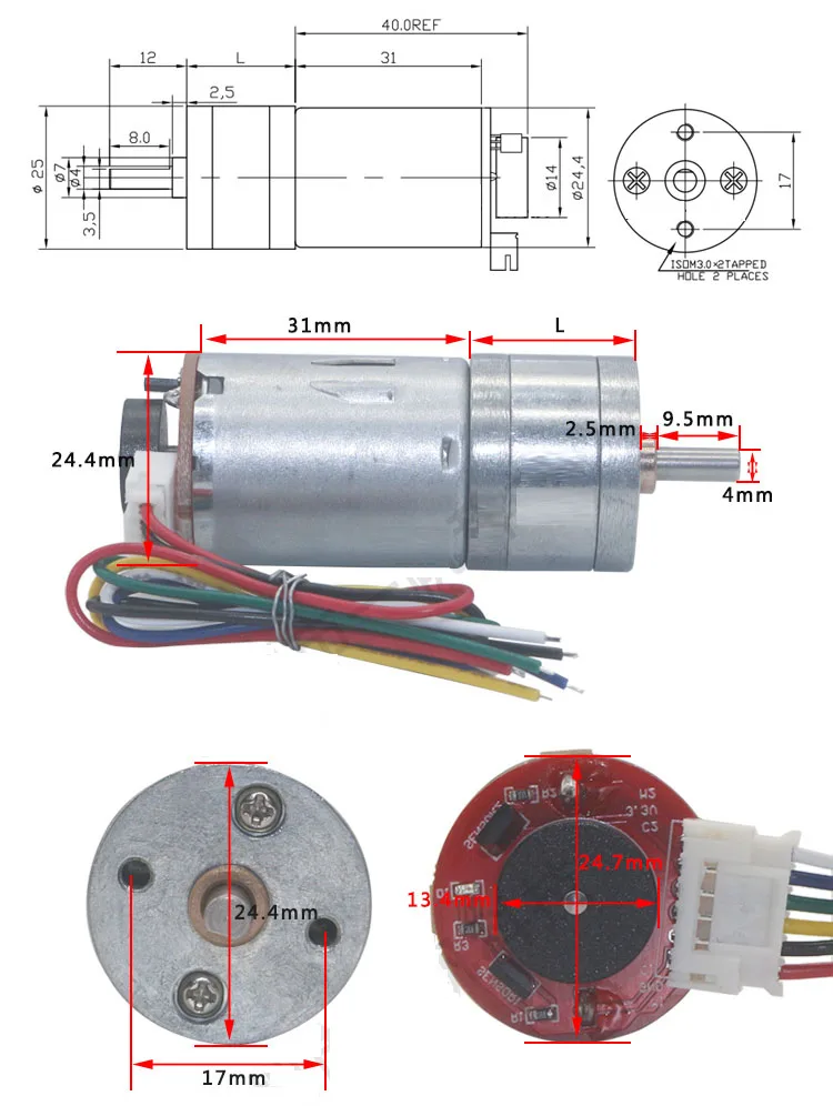


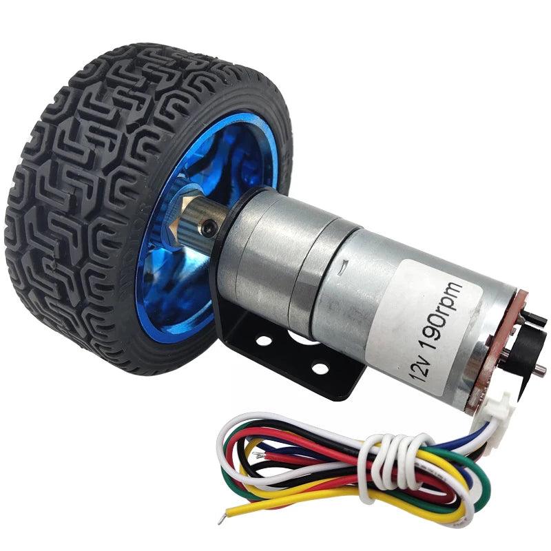
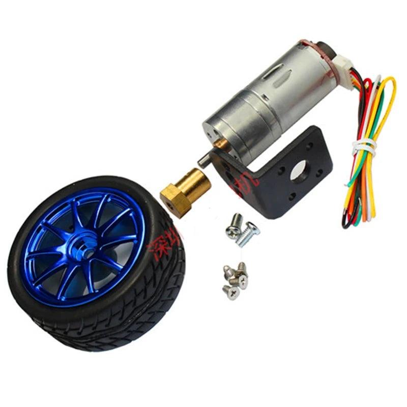
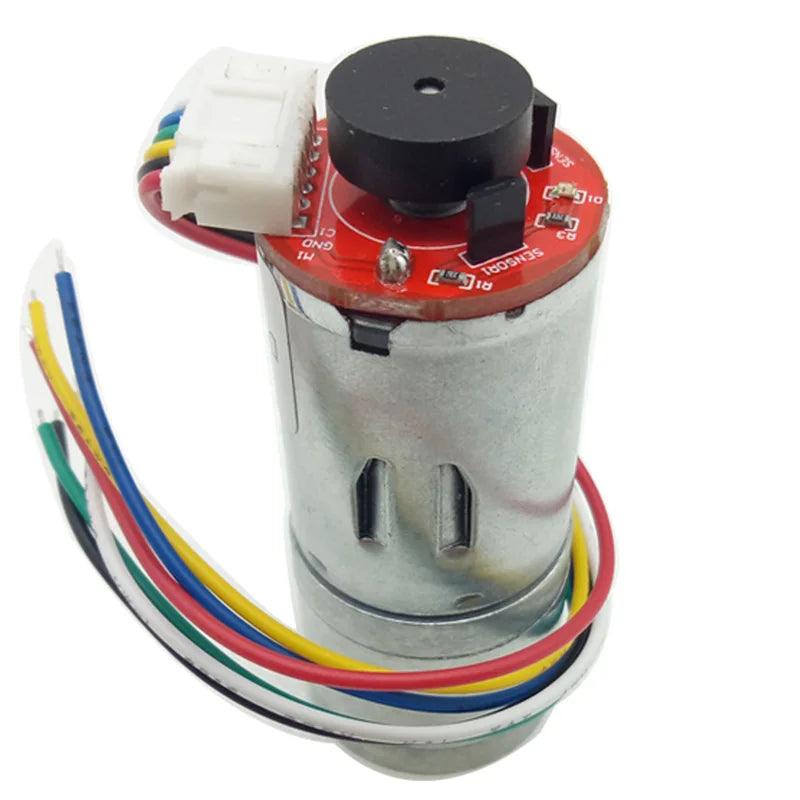
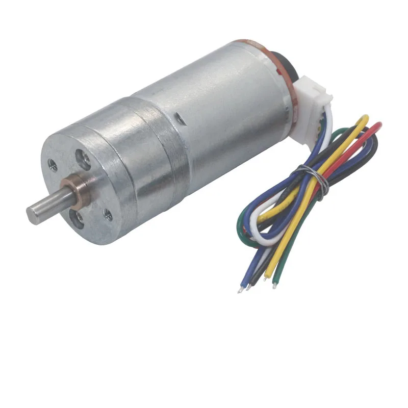
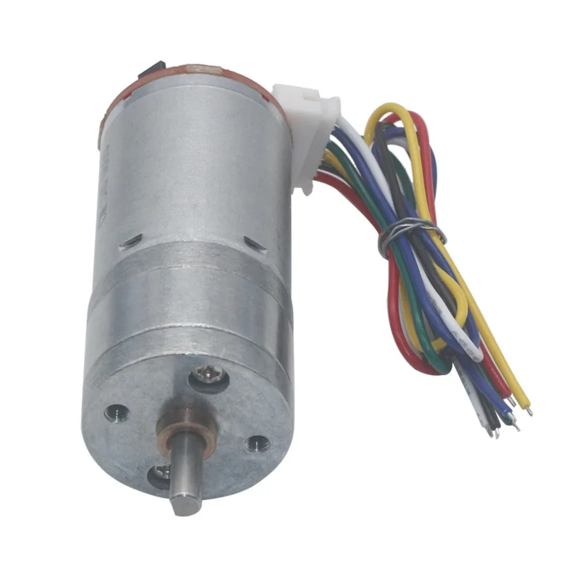
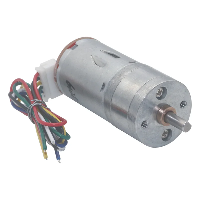
The following is the picture of the motor


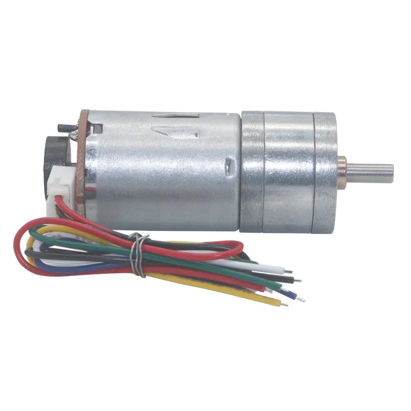
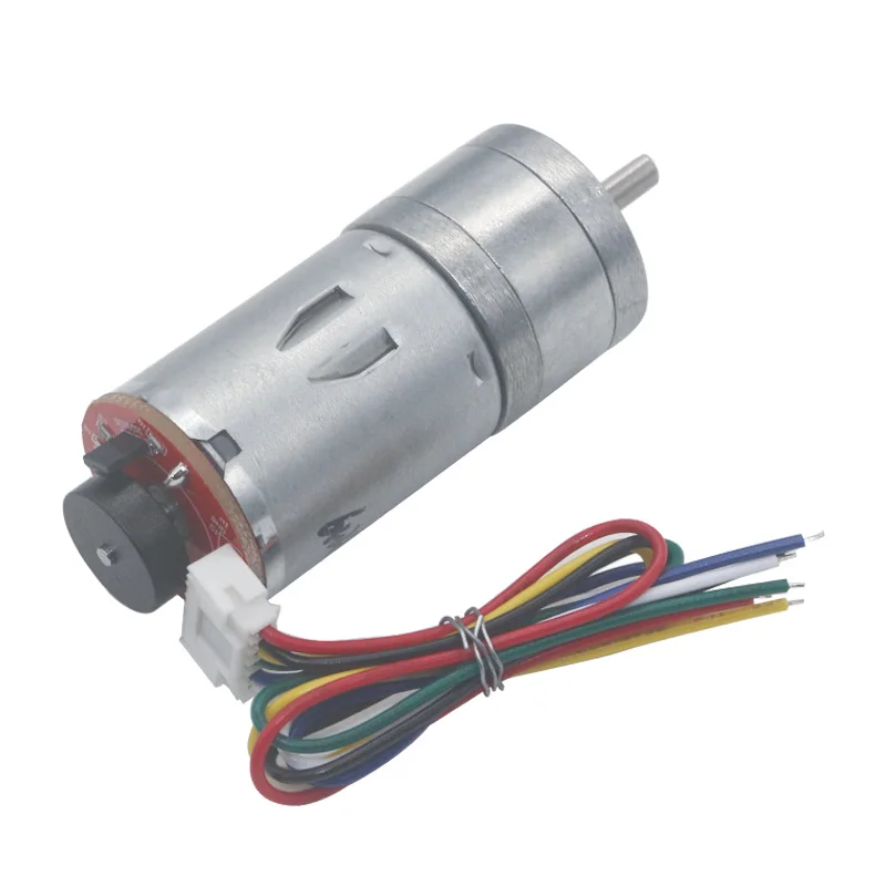
Wiring method:
-
Red Wire - positive power supply of motor(+)(change positive and negative of motor the rotation will change)
-
White Wire - negative power supply of motor(-)(change positive and negative of motor the rotation will change))
-
Yellow Wire - signal feedback (motor one turn has 11 signals)
-
Green Wire - signal feedback (motor one turn has 11 signals)
-
Blue Wire - positive of encoder power supply(+)(3.3-5V),cannot be wrong
-
Black Wire - negative of encoder power supply(-)(3.3-5V),cannot be wrong
Care Instructions
Care Instructions